This was not my first major modification project (my first was an old Presonus MP4 headphone amp, AMAZING, which I might write about another time), but it was significant insofar as these are my studio monitors, and I basically wasn’t using them. They’re just not clear enough. Muddy and incoherent, kinda bland, can’t hear anything clearly, tried some corrective EQ, only mitigates. I primarily work with classical and acoustic stuff, so quick and snappy good. I know the Rokits are favorites of EDM folks, I don’t really care about that stuff (sorry), but these were my first monitors and I didn’t know any better…
Anyway, I’ve been interested in audio modification for a while, and the arguments that swirl around them––rather than constantly buying new stuff, buy used stuff on its way to the garbage bin, pimp it out, and end up with a device that rivals high-end gear. It makes complete sense to me that a company with a profit margin, like KRK or Presonus or M-Audio or RME, would cut corners where they think it’ll be least noticed by 95% of folks in most normal-use situations (i.e., a singer-songwriter at home on their bed crooning into some crappy Chinese mic). It shouldn’t be wrong to “tune” your equipment to sound the way you want.
To me the mindset is very much like what people think about in the instrumental world. I grew up with a Yamaha G2 grand piano, a rather petite instrument, about 5’7″ or so. Yamaha makes spectacularly reliable actions, but the sound usually leaves something to be desired. The hammers were rock solid (not in a good way), so when I was in college we had a piano technician replace them with a set custom made for the piano by Ari Issac in Toronto. The new set completely transformed the sound––there was color, finally, shading, resonance, a dynamic range (especially soft)––and over a decade later those hammers continue to break in, revealing new sounds I never thought I’d hear from such a small instrument. Recently I had the bass strings measured for replacements. Yamaha is not known for making great bass strings––they sound a bit like surgical tubing drawn taut. I haven’t yet heard the results, but I will when I return home to visit my family for the holidays. Anyway, modification is a very musical thing to do, so I don’t think people who are interested in modifying their audio equipment are somehow phoolish to think they can eke out every last drop of good sound. Your milage may vary, and that’s ultimately all that matters.
Okay, if you pay $50 for one capacitor made with raw sheep’s milk or whatever, you are an idiot.
Anyway, I wasn’t using these Rokits much, plus the warrantee was out. What could go wrong?
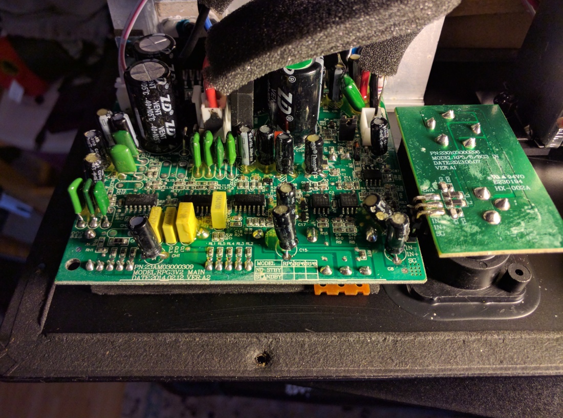
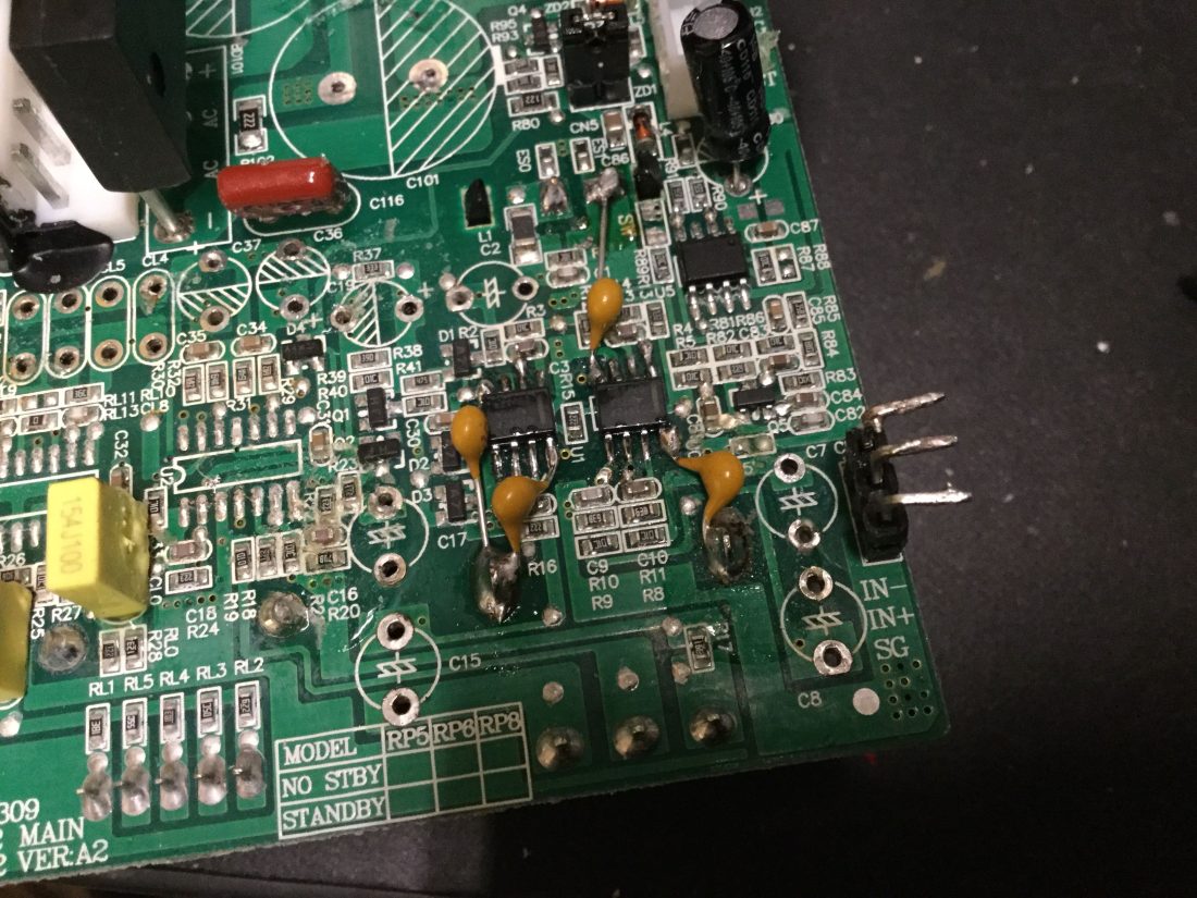
Nothing wrong with them. They work just fine. This is the internal amp I was going to modify. The actual amplifiers are two integrated circuits (TDA7296, one for tweeter, one for woofer) pasted to the heat sink in back, the rest of this circuit is power supply, input buffer, and crossover. Power supply in the back (large capacitors and rectifier), input section in the front right using bipolar caps and two NJM4580s, crossover section in the middle front left uses three TL074 (and the green mylar caps). The yellow caps up front appeared to be for the corrective filters on the back, and I never use that function, so I figured I’d leave them alone.
Only way to remove the amplifier board was to desolder it from the input PCB. Definitely ripped a pad here, but it wasn’t a problem to repair later (just used a jumper or something).
[There’s also a “mystery circuit,” seen just to the top left of the input board that appears to supply 5V for a digital… something. Wasn’t connected to anything, so I wonder if KRK has another line of bluetooth products that use this amplifier board? I couldn’t find any. I left it alone. EDIT: if you check out my next post about this, I discovered this is part of the mute/standby and limiter circuit, both of which I figured out how to disconnect!]

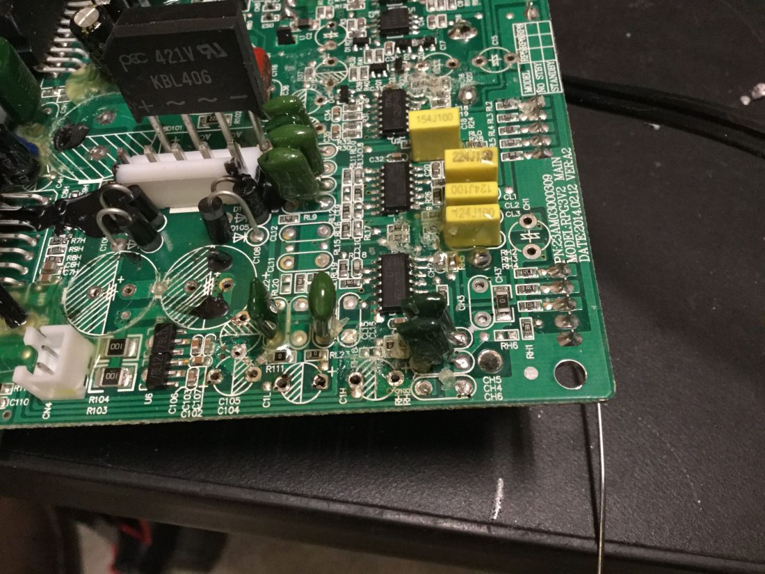
The electrolytic caps are all easy to replace. They all have capacitance and voltage ratings written on the case––you can go bigger on both, just not smaller, but remember you’ll have to deal with larger cans. The mylar caps are another matter. They didn’t seem to have much of anything written on them, plus everything was bathed in a disgusting sticky glue which seemed to obscure any writing that may have been there. I used a capacitance meter to measure each cap after I removed it.
(apologies for the chicken scratch, and no offense to chickens)

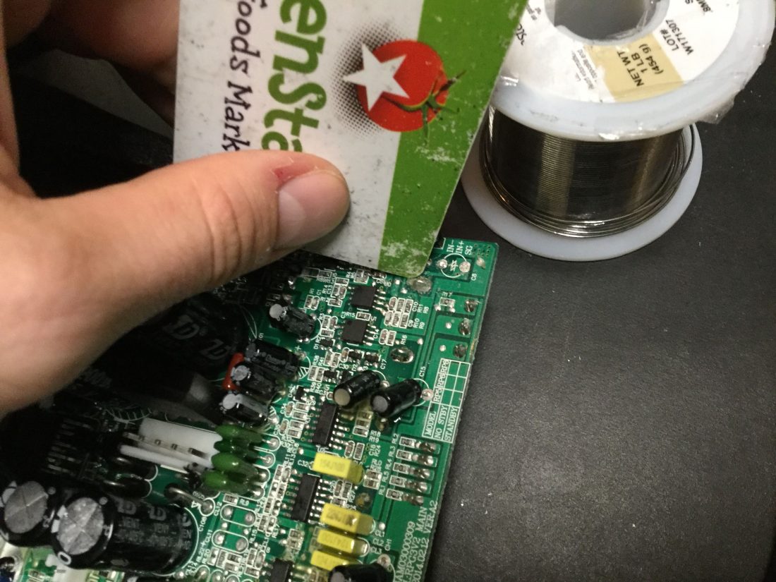
Couldn’t be exactly sure what the value was of each cap (they have a tolerance that usually is within 20% of the stated value), but rounding to the closest available value on Mouser or DigiKey usually revealed what they must have been.
Another view of the mylar caps (green).
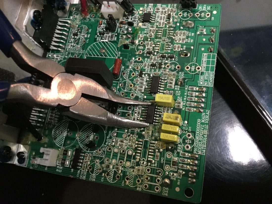
To remove the op amps I very gently grasped them with a pair of pliers and used a hot air rework station to melt the solder––add some flux paste around the pins to lower the melting point of the solder. There’s no need to pull, the chips weigh nothing, they basically float up off the pads the moment the solder melts (which usually takes about 5-10 seconds).


Clean board (all the SMD resistors, diodes, capacitors are left in place, of course):

Now had to remove all that glue:
Added extra supply rail decoupling, 0.1uF ceramic capacitors from each power rail to ground. Seemed there was one ceramic cap between the rails for both input opamps, extra won’t hurt, and would certainly help prevent stability problems when I put in the faster opamps. I used OPA1642/1644––FET input opamps, safe replacements for NJM4580. The OPA164x family is, according to TI, descended from OPA2134 (a popular chip among modders, since it can pretty much replace anything without causing issues), with lower self-noise and current consumption.
The basic guideline for choosing replacement opamps is pretty simple: you can generally use a FET input opamp to replace anything. The quietest opamps out there, speaking in terms of their inherent self-noise, are bipolar opamps (OPA1612 is TI’s flagship, but the NE5532 is the ‘classic’ example), but they tend to be a little fussier and will oscillate if they’re not situated in a complimentary circuit. A lot of this has to do with opamp’s inherent resistance to current, or input impedance, which relates to the bias current of the input transistors in the chip. FET opamps use FET transistors at the input, which require very little bias current, so the input impedance is very high, 10s of megaohms. Bipolar opamps require more current flowing across the input transistors, so their input impedance is necessarily lower, 20kohms or so (some bipolar opamps like MC33078 or NJM4580 have higher input impedances, 200kohm to 5megaohm range, but these are are chips I tend to replace…). I could have used the very quiet OPA1612 (20kohm input impedance) at the input here, since the input impedance for this circuit is only 10kohms. Provided the power supplies are properly decoupled (as I’ve done), it would probably be stable, but the problem is that this chip only has low self-noise at relatively low impedances. The higher the input impedance, the more noise at the input, and extra expense becomes self-defeating, as you can see in this graph.
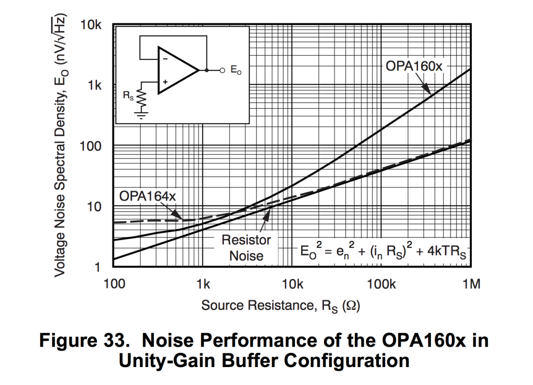
At 2kohms and below, the bipolar chip (in this case, the OPA160x series) has lower self-noise than the FET input OPA164x, but above that, as the current across the input transistors drops, the chip becomes noisier. So using a fancy chip like OPA1612 in this kind of setting, at $7/ea, doesn’t really make sense.
So, onwards, I replaced all polarized electrolytic caps with Panasonic FR, and bipolars with Panasonic SU. I kept all the values the same, although, come to think of it, I might have done well to at least double all the signal path caps, especially because I bypassed every one with a polypropylene film capacitor (also Panasonic, though I can’t remember which type). Mylar crossover caps were also replaced with Panasonic polypropylene. A couple values weren’t available on Mouser, so I used a Vishay polypropylene cap. Were I to do this again, I’d use WIMA MKP/FKP, I just didn’t know where to look when I did this.
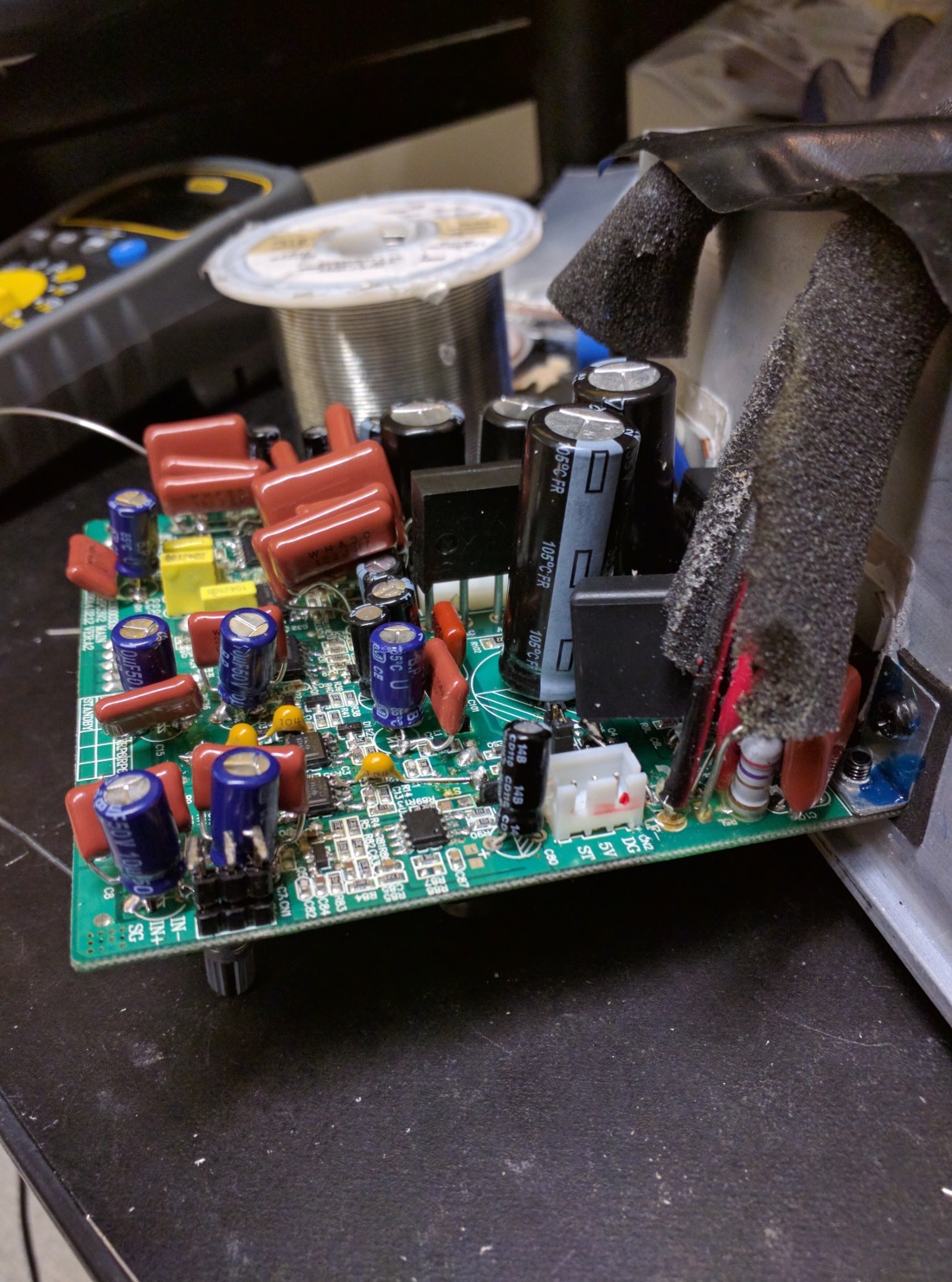


So I plugged it in and… no smoke! So how does it sound? I placed both speakers side by side (as pictured at the top of the page), one modified and the other stock, plugged them into the two outputs of my interface and routed an identical mono mix to both (I think it was of Mitsuko Uchida playing a Mozart concerto). “Panning” back and forth between the channels, the difference was NOT subtle. One gave the impression of having a wet towel wrapped around your head, the other didn’t and sounded like music. In fact, more than that, in the modded speaker I could perceive a sense of horizontal depth even with a mono signal, like distance front-to-back between instruments on the stage. That surprised me. So yeah, it was worth it. I modded the other one promptly.
These are the 5-inch speakers, so they still have a limited low end. I’m not sure increasing signal path cap sizes would have helped that much. I understand there is a limiter circuit built into this amplifier somewhere that could be disconnected (EDIT: I did it). Again, I don’t listen to EDM or anything with super heavy bass that could blow out the voice coils, so I’m not worried about damaging the speakers, plus I’ve heard of folks doing this in the Yamaha HS8s to great effect. Finding it would be a matter of poking around with an oscilloscope, so maybe I’ll do this at some point.
So how do they compare to other more expensive speakers? I don’t know, I don’t own anything else (I compared them to some Mackie 828s, which got smoked by my KRKs, but that was unfair because the Mackies are inherently slow and noisy), haven’t done a side-by-side with someone who does. [EDIT: you know who has is this guy, who used to be a head modification designer at Black Lion Audio. He mods these speakers professionally, and others, has done comparisons with hi-end stuff like Genelec and says these modded KRKs hang right in there, and represent the absolute best value in terms of the sound you get!]

Hello. Interesting mod. I haven’t tried it yet – all comes down to warranty. May never.
One question I have, not sure if you can answer. What is the shorting block on the board used for? My Rokit 8’s Gen 3’s have the same jumper. I’m currently looking for ways to disable/bypass the auto-standby. Gibson was apparently telling some people how to bypass the standby, but then stopped.
A lot of people would be interested in bypassing the auto standby. It appears to be the single-most biggest complaint about these monitors.
LikeLike
If you remove the jumper, the amplifiers seem to be completely disabled. Might be a diagnostic tool for testing the circuit with the speakers still connected. I can’t remember the amplifier IC models, but from what I remember from the datasheets, I believe the auto-standby feature is built directly into the amplifier chips themselves, and the time on/off is regulated by capacitor size.
You’ll find that on p. 5, for C3 and C4: https://www.st.com/resource/en/datasheet/tda7296.pdf. Looks like decreasing the size of those capacitors will make the stand-by/mute time shorter, although that may have more to do with the ramping speed.
Looking at this now, I feel like I should revisit some capacitor value choices…
LikeLike
Thank you for responding.
Thanks for the link to the datasheet. Very interesting.
I just searched for the TDA7296 and standby, and this amplifier is used by other speaker brands, all with equally stupid (or worse) auto-standby.
One brand in particular has a 15 minute auto-standby. That would drive me even more nuts than a 30 minute auto standby.
I might make a simple mod at first that lets me easily swap out the resistors and capacitors, try different values. Apparently there is a timing order to which mute and standby must work in order to avoid pops and possible screeching.
I understand from continued readings that EU regulations mandate auto-standby be enabled with no defeat/adjustment switch. Well, that’s not going to work for me. Besides, I’m in North America, so EU regulations can kiss my behind.
If I come up with anything useful, I’ll be sure to share with you.
Thank you.
LikeLike
Hey, yeah! Let me know what works for you! I might try it out myself…
LikeLike
Les from Cape Town, I have KRK Rokit 6 G3 which powers on but no audio at all.
I have checked the mystery chip pin 4 has zero V until I supply audio signal then it goes to 5 V but still no audio, I have checked all soldering and visual check of all components but all appears to be OK. Even tried all 3 inputs (RCA, TRS and XLR) The other KRK works correctly Don’t believe it’s the TDAs as both HF and LF are unlikely to be the culprit.
I read your mod regarding auto-mute and peak limiter but again, don’t think it’s the issue as the chip is supplying 5V on pin 4,
Any ideas would be very welcome
Les Cooper
LikeLike
I’d also be interested if someone figures out a way to disable or bypass the standby. I can understand energy saving features in many products, but jeez, not in studio monitors.
LikeLike
I haven’t forgotten to dig more into defeating the standby feature. I had to put it on the back burner due to other more pressing issues. I do want to solve this problem and publish the solution.
LikeLike
I’m another very interested party in disabling the Auto Standby… I had a crack myself with limited knowledge of electronics.
There seems to be two stages to the auto standby, there is a relay that seems to be fed by something on the main circuit board (that runs off a low power 5v charger like psu) which gives the amp power (the on click), but even with the relay forced on, below volume thresholds no sound makes it through the amp (KRK lights are on at this point, no sound tho). A second volume spike above the threshold is needed to trigger something in the more complex circuits on the main board, sounds like the amp chip you’re talking about.
Obviously I’m way out of my depth, but this problem is mega annoying and would love if you guys could come up with a hardware hack for this. Every time I turn my volume up from zero I have to overspike it for a second to make sure its awake and quickly turn it back down so it doesn’t start mega loud.
LikeLike
Sup folks, figured it out. Check out my newest post.
LikeLike
Thank you for looking into it.
So, it seems like, if I only want to bypass the timed mute/standby and not bypass the limiter, I probably want to lift the top pin of the BPT and tie it high.
Does your mod bypass the power-on mute/standby delay on power-up? (eg: do you get a loud pop at power-up?)
I’ll have a look at the circuit when I’m back in my speakers. Hopefully I can trace it back to the power-up delay circuit.
I’m not opposed to defeating the limiter, just not sure if I want to. I listen to and compose electronic music, as well as play games, and don’t want to damage the drivers.
LikeLike
Nope, a couple of the capacitors around the amplifier chip gradually ramp the standby circuit on or off, so it’s safe (at least it was for mine! I checked with an oscilloscope)
And if by top pin, you mean pins 3+4, then yes, I think so. Just make a solder bridge between them.
And yes, if you listen to electronic/explosions, then probably not a good idea to defeat the limiter! These speakers work great for that stuff. They’re pretty useless for classical work, which is why I went to all this trouble…
LikeLike
Hi minimaliszt,
Ok, so ignore the transistor, and short the mystery IC. Got it. I’ll give it a try this weekend, and see how it goes. Simple mod. Will report back.
LikeLike
Hello minimaliszt,
Sadly, shorting the two pins on the IC didn’t work. No sound is output. Too bad that IC doesn’t have any ID on it, it would certainly help.
I’m going to undo the mod, then do some more research.
Meanwhile, if you have any other thoughts, let me know.
LikeLike
Well, I removed the IC entirely, then shorted the pins, could be it’s still sinking current, or whatever it does… maybe you could try that, but only if you’re really confident with your soic removal skills.
Yeah, seriously, no id is a real cheapshot.
Otherwise, basically what needs to happen is that pins 9/10 of the amplifier chip get a perpetual supply of 3.5V or higher in order to stay on. I considered finding this elsewhere on the board and running it directly to the standby/mute circuit’s bypass el-caps, but then I discovered the shorting trick.
LikeLike
Yeah, I was considering removing the IC entirely. I have a heat gun with a small nozzle, so removal should be relatively easy. If it is a dual logic IC, then I wonder what the second logic gate is used for. Perhaps one to control the standby, and the other is involved with the limiter.
I might also try removing the IC, then soldering it back in partially with wires – by connecting each logic gate individually, I can see/hear/smell what happens (doubt smoke would come out, but I guess I’m always expecting it).
I noticed the board has printing on it where the manufacturer can ID which speaker the board is for (6, 8, 10), and whether the board is configured for standby or no standby. Teasing me 🙂
I think I’ll take a look at the amp IC’s and the capacitors too – hopefully that section is exactly like the schematics for the G2’s. I was studying those schematics last night, but I was having a hard time figuring out how the standby/mute caps were being driven. I dabble in electronics, by no means an expert.
Thank you for the help and insight.
LikeLike
I found a SW pad near the IC, so I probed it. One side is tied to pin 3 of the IC. The other side is tied to ground. I decided to bridge the two pads, and no more output. Hmmm, that won’t do it. Will continue working on it.
LikeLike
I have a case for KRK rokit G2 , can use replacement board from KRK rokit G3 with G2’s front speaker and twitter? I know the holes on the backplate don’t align with the G2’s hole, but I can drill them in.
LikeLike
I don’t know how to express my thanks/ heart-felt gratitude to you. You just saved my life with this blog post.
I bought KRK ROKIT 5 G3 with much hope by spending a fortune ( in terms of my own financial credential ). One of the speakers suddenly died just after the expiration of the warranty period. There was no service centre in my country. I tried my best to fix it but alas; all my earlier DIY knowledge of building Gainclone, 3 Way Active Crossover and countless electronics projects failed. Due to my aging process I am slowly losing my vision and the enthusiasm to minutely inspect a pcb/ circuitry. I felt so helpless and became depressed.
I was planning to switch over to headphone monitoring and mastering of my works as a last resort as I couldn’t afford another pair of studio monitor. I found your website luckily and with your kind and meticulous guidance, things became crystal clear to me. The monitor is fixed now! I only had to change that “mysterious IC” and things started working again.
Thank you a ton once again for this life saving post. Keep up the good work! God bless.
Kindest regards,
Som
LikeLike
Wow, thanks, this is very kind… I’m glad it helped you! I understand the feeling of helplessness, I don’t understand why these companies make it so difficult to get schematics or other info that would actually help people repair their own equipment. The marketplace literally wants you to trash your gear and buy new stuff, and that mindset is ruining the planet. Hope everything continues to work for you!
LikeLike
Hi.
I’d like to know, when you say changed that mysterious IC, you replaced it, removed it, or modded it?
Thank you.
LikeLike
Remove!
LikeLike
Do you play electronic music, and have you noticed any undesirable effects after the mod? I would like to try removing the IC, once I get my hot air soldering station.
LikeLike
I do work with some electronic music, but probably not the kind you’re thinking of… if you’re doing a lot of EDM stuff, I *don’t* recommend the limiter/standby/bypass mod. The limiter is there to protect the speaker against overages, and EDM, with its super punchy low end, would probably damage the voice coils in pretty short order. I’d say the limiter/standby mod is only worth doing if you listen to lots of detailed, quiet music (classical/jazz/folk, e.g.).
But yes, I noticed tons of improvement! I love my modded KRKs.
LikeLike
Any idea what would cause +2v DC surge on woofer (goes away in a few secs and crackles for a minute). Ive replaced large caps. Sound is good through speaker but this jolt of DC pushes speaker out for a second and makes a loud buzzz (which cant be good for the voice coil). Cant see any components with issues and traces look fine… all the black goop is cleaned off. Wondering if it isnt easier to jsut use some large caps and create a dc block on the + woofer side?
LikeLike
Ugh! That sounds awful! Is this G2 or G3? There’s no black goo in G3 (well, not as much anyway), and there’s definitely interstage ac-coupling, so I’m gonna guess it’s a problem with the amp chip. You have a scope?
LikeLike
Les from Cape Town,
I have a KRK Rokit 6 G3 that turns on but produces no sound at all. I have checked the main circuit board for soldering and components and all appears to be good. I checked the voltage at pin 4 of the Mystery chip and it reads 0 V, when I apply audio signal via RCA or TRS input it goes to 5 V so don’t believe the auto-mute/limiter circuit is at fault. Also don’t think the TDAs are at fault as it’s unlikely that both HF and LF would fail. The other KRK works perfectly. I have removed and tested most of the caps and all are to spec.
Any clues as to what the problem might be?
Thank you,
Les
LikeLike
Wow I am slow, apologies for keeping you in suspense here. This year has been… well, you know.
Ugh, man, there are so many things that could go wrong with these speakers. Do you have an oscilloscope? I think tracing the circuit is really the only way to figure out what’s going on, pipe in a sine or square wave and try to follow it to the amplifier chips. You can even do this with a multimeter in AC mode, if you haven’t already.
I’m sorry to not have any better ideas. This sort of thing is singularly frustrating.
LikeLike
I’m also trying to solve the auto-standby problem. Has anyone figured it out???
LikeLike
For those that don’t want to do a lot of modifications in order to disable the auto power off feature of the KRK Rokit G3 monitors, check out this link:
https://www.eevblog.com/forum/repair/krk-rokit-5-g3-how-to-permanently-disable-the-auto-power-off-feature/
One jumper wire, and it’s defeated. Tested on my KRK Rokit 8 G3’s. Success!
LikeLike
How repairable is this third generation compared against the previous G2 models? I’ve seen about the black goo of death in the G2 but now the G3 uses SMD components so that makes me wonder about repairability.
LikeLike
Yes, they removed the black goo of death, and of course SMD components can be difficult to replace, but if you have a hot air station it’s really not a big deal and sometimes even easier than having to wick out each through-hole pin one by one. Nice thing about G3 is it’s all on one board, but things are obviously smaller.
LikeLike
Do you happen to have a schematic for the R5 G3?
I ask as I have one that stopped working after a power surge. Power is still on the unit BUT no audio. My 2 thoughts were either a MUTE issue or both TDA’s non functional.
Thanks
LikeLike
Hey Russ,
Unfortunately no… I think I found a schematic for G2, in part because I wanted to get info on the limiter design, but I couldn’t find G3. It’s a tricky board to probe because everything is so crammed in together. Have you checked the power supply pins on the TDA’s? You might see if you can input a sinewave and trace it through the board, at least through the opamps at the front end.
LikeLike